本篇以 HTU21D 溫度與濕度感測器與 MPU-6050 加速度計與陀螺儀六軸感測器為例,示範如何在一張樹莓派上同時連接多個 I2C 設備。
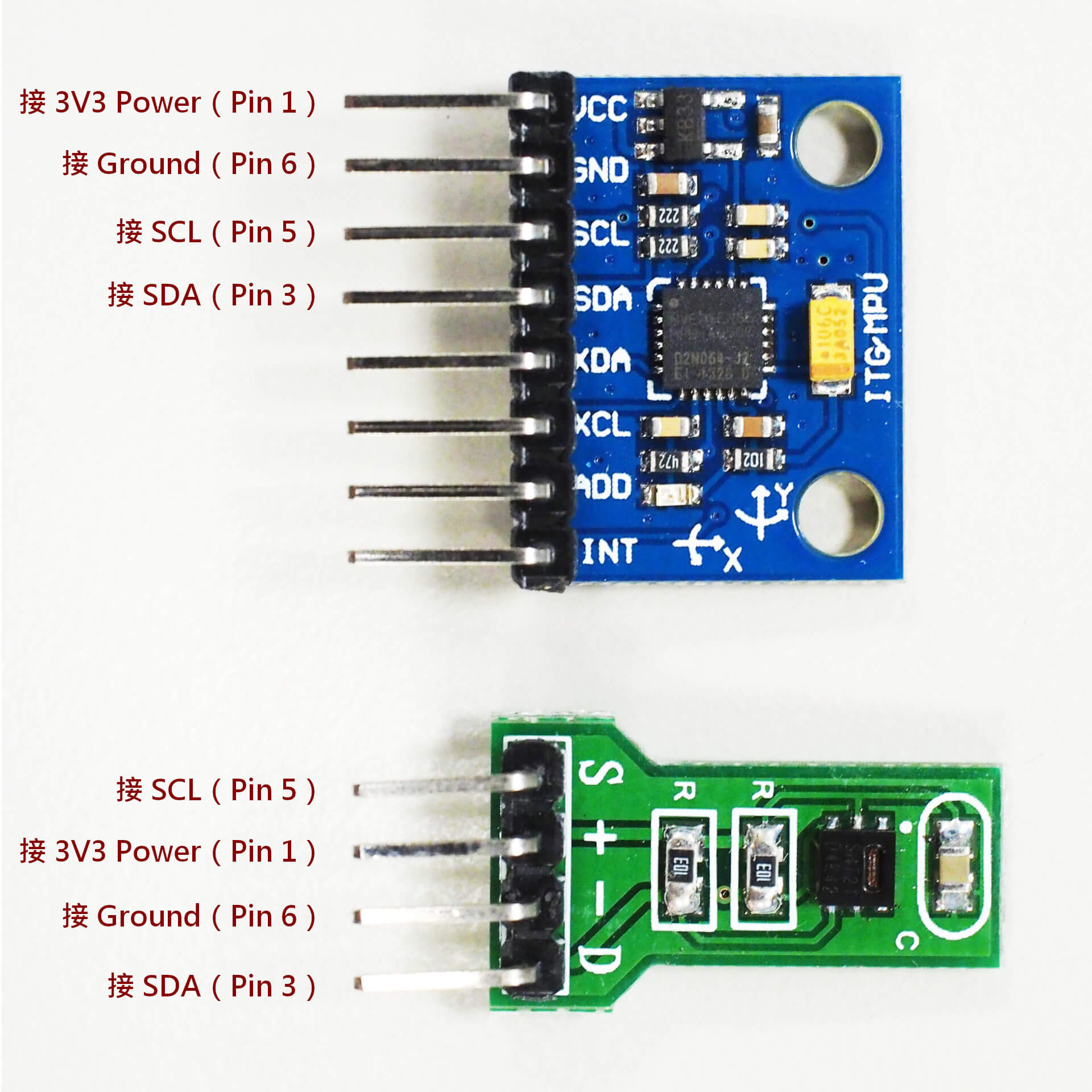
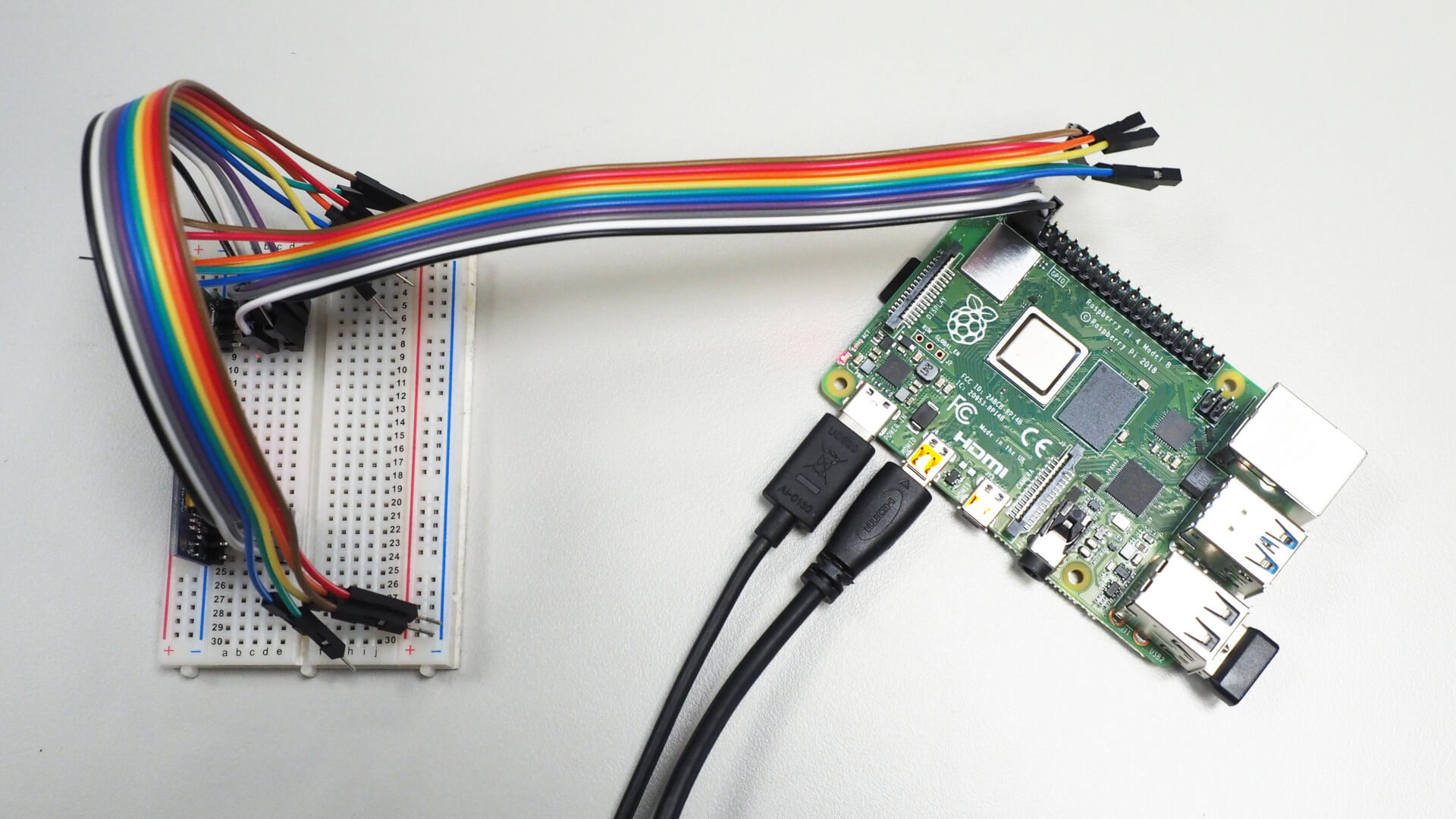
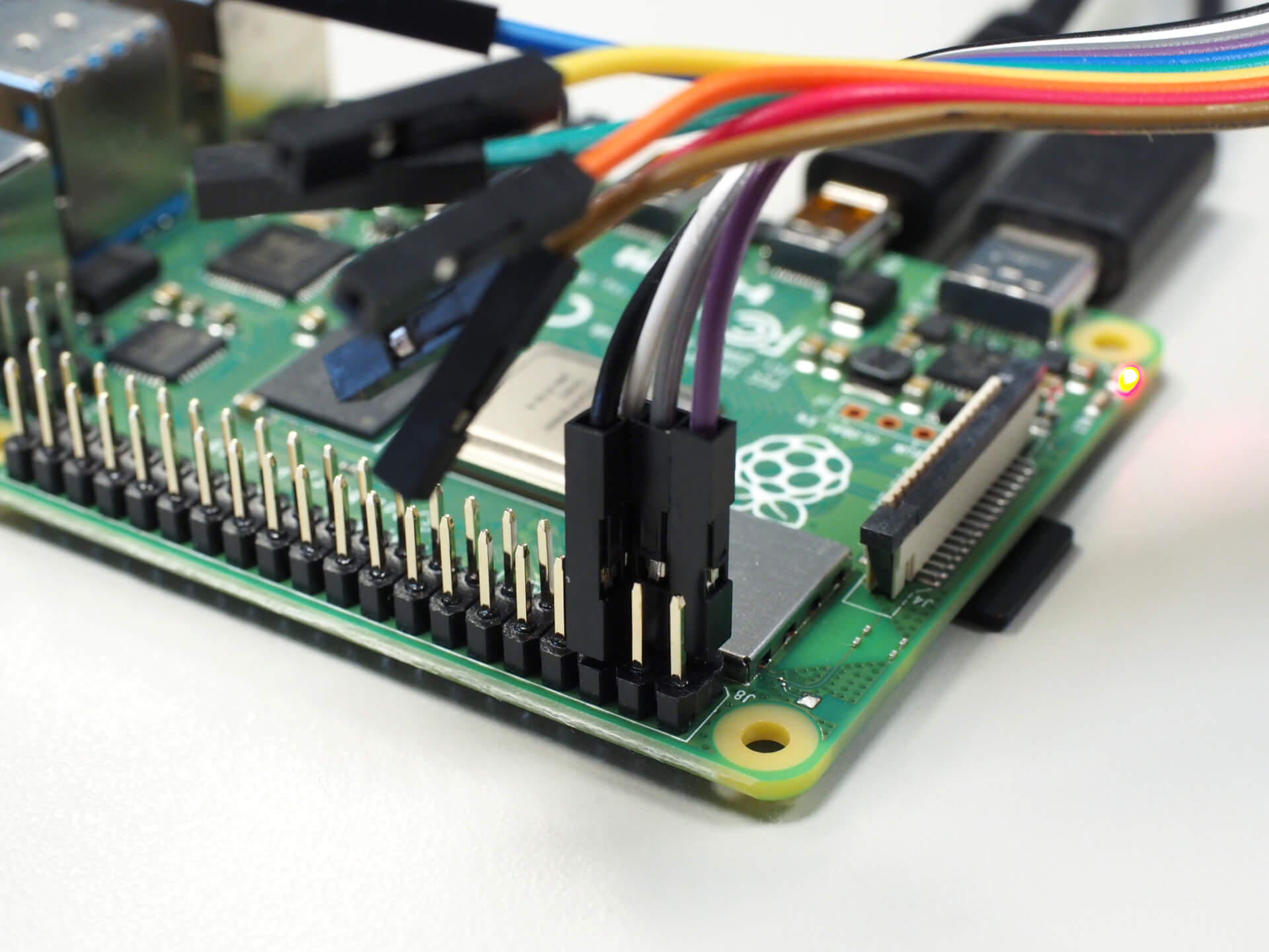
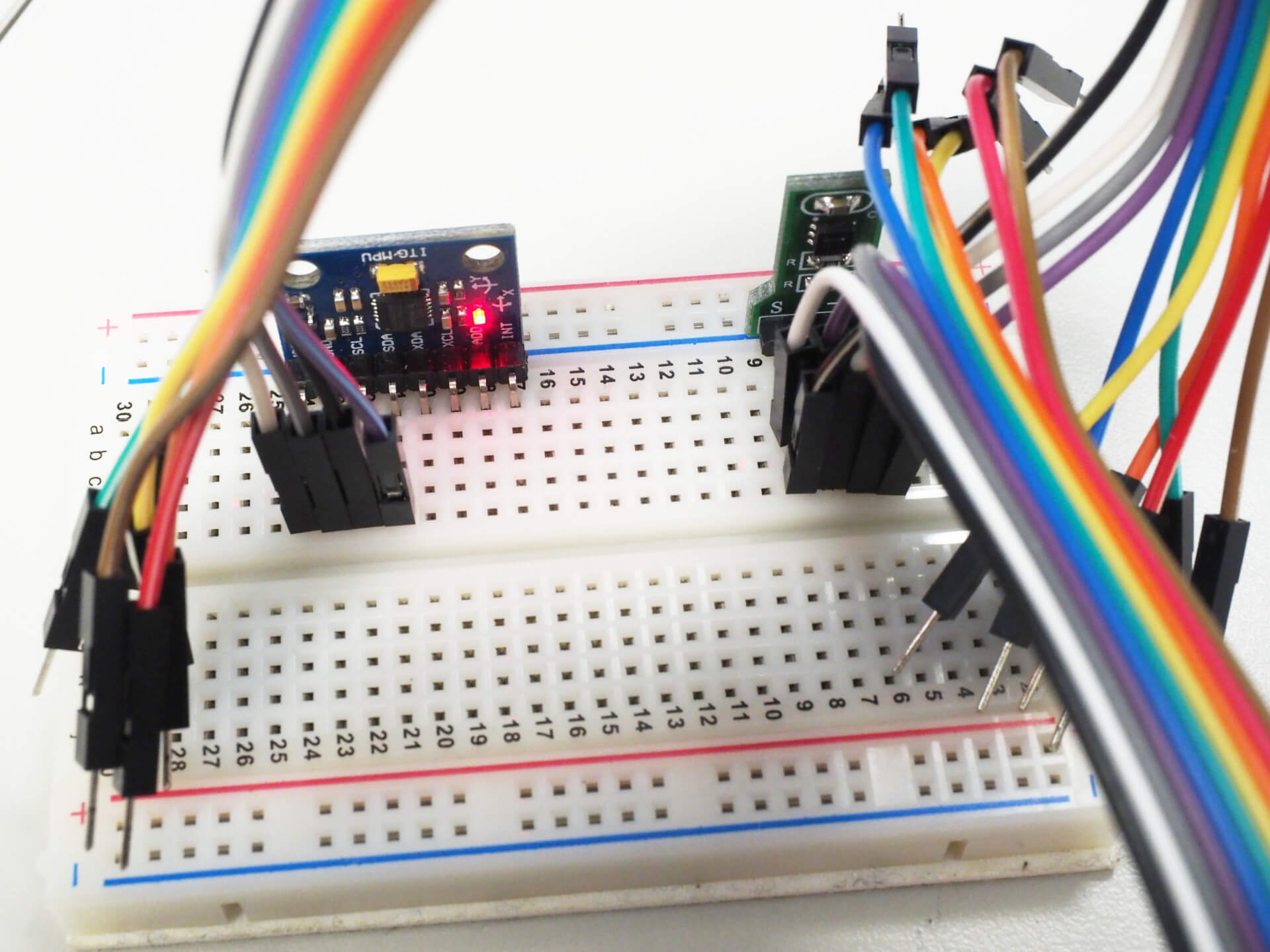
若要在樹莓派上同時接上多個 I2C 裝置,只要各項裝置的 I2C 位置不同,就可以直接並聯接在同一個 I2C 匯流排(bus)上,也就是將各 I2C 裝置的 SCL 與 SDA 兩條線都接在同一個腳位上,而電源的兩條線也都可以共用,所以最簡單的接法就是四條線都共用相同的腳位。
這裡是將兩個不同位址的 I2C 裝置放在同一個匯流排上,如果遇到相同 I2C 位址的裝置,就無法使用這樣的方式,必須改用不同匯流排的方法來處理,請參考本文下方的說明。
由於樹莓派的 I2C 腳位上本身就內建一個 1.8k 歐姆的上拉電阻(pull up resistor),所以在連接 I2C 裝置時就不需要另外接上拉電阻了。
接線前記得要先將樹莓派關機,接好之後再連接電源開機。
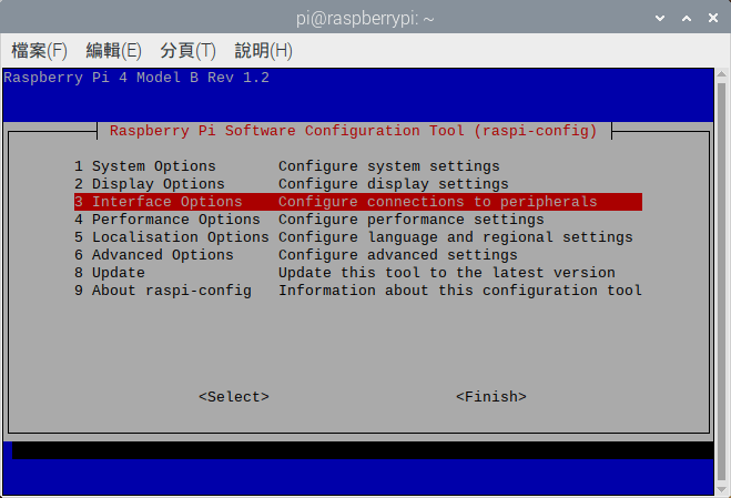
在樹莓派初次使用 I2C 前,要先執行 raspi-config 設定程式,啟用 I2C:
# 安裝 i2c-tools 套件
sudo raspi-config
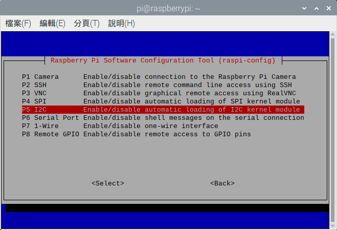
執行之後,選擇「Interface Options」。
選擇「I2C」後,啟用 I2C 功能。
i2cdetect 檢查 I2C 位址將 I2C 設備都接上去之後,要先以 i2cdetect 工具指令檢查各裝置的 I2C 位址,使用前先安裝:
# 安裝 i2c-tools 套件
sudo apt-get install i2c-tools
再以 i2cdetect 查詢 I2C 裝置位址:
# 查詢 I2C 第 1 匯流排各裝置位址
sudo i2cdetect -y 1
     0  1  2  3  4  5  6  7  8  9  a  b  c  d  e  f
00:          -- -- -- -- -- -- -- -- -- -- -- -- --
10: -- -- -- -- -- -- -- -- -- -- -- -- -- -- -- --
20: -- -- -- -- -- -- -- -- -- -- -- -- -- -- -- --
30: -- -- -- -- -- -- -- -- -- -- -- -- -- -- -- --
40: 40 -- -- -- -- -- -- -- -- -- -- -- -- -- -- --
50: -- -- -- -- -- -- -- -- -- -- -- -- -- -- -- --
60: -- -- -- -- -- -- -- -- 68 -- -- -- -- -- -- --
70: -- -- -- -- -- -- -- --
這裡顯示在第 1 個 I2C 匯流排上,0x40 與 0x68 這兩個位置有裝置在使用,而 0x40 就是 HTU21D 溫度與濕度感測器,0x68 則為 MPU-6050 加速度計與陀螺儀六軸感測器。
事實上不管有幾個 I2C 裝置,只要位址不同就可以放在同一個匯流排上,後續讀取各個感測器資料的方式都跟一般的做法相同。
若要讀取 HTU21D 溫度與濕度感測器的資料,可以使用 adafruit-circuitpython-htu21d 模組:
# 安裝 adafruit-circuitpython-htu21d 模組
pip3 install adafruit-circuitpython-htu21d
以下是讀取 HTU21D 溫度與濕度資料的範例:
import time
import board
from adafruit_htu21d import HTU21D

# 建立 HTU21D 感測器物件
i2c = board.I2C()
sensor = HTU21D(i2c)

# 讀取 HTU21D 溫度資料
print("Temperature: %0.1f C" % sensor.temperature)

# 讀取 HTU21D 濕度資料
print("Humidity: %0.1f %%" % sensor.relative_humidity)
Temperature: 22.4 C
Humidity: 60.0 %
mpu6050 是一個可以讓樹莓派讀取 MPU-6050 加速度計與陀螺儀六軸感測器的 Python 模組,使用前先執行以下指令進行安裝:
# 安裝必要套件
sudo apt install python3-smbus

# 安裝 mpu6050-raspberrypi 模組
pip3 install mpu6050-raspberrypi
接著使用 mpu6050 模組讀取 MPU-6050 的資料:
from mpu6050 import mpu6050

# 建立 MPU6050 物件
sensor = mpu6050(0x68)

# 讀取加速度計資料
accel_data = sensor.get_accel_data()
print("Accelerometer data")
print("x: " + str(accel_data['x']))
print("y: " + str(accel_data['y']))
print("z: " + str(accel_data['z']))

# 讀取陀螺儀資料
gyro_data = sensor.get_gyro_data()
print("Gyroscope data")
print("x: " + str(gyro_data['x']))
print("y: " + str(gyro_data['y']))
print("z: " + str(gyro_data['z']))

# 讀取溫度資料
temp = sensor.get_temp()
print("Temp: " + str(temp) + " C")
這段程式碼執行之後,就可以讀取並輸出 MPU-6050 感測器上的各項資料:
Accelerometer data
x: 10.105925207519531
y: -0.2059013427734375
z: -0.6727706665039062
Gyroscope data
x: -1.083969465648855
y: -1.2595419847328244
z: -0.3816793893129771
Temp: 23.306470588235296 C
如果遇到兩個裝置剛好使用同一個 I2C 位址的時候,就無法將兩個裝置接在同一個 I2C 匯流排上,而需要採用分開的 I2C 匯流排來處理。
樹莓派本身有 i2c0 與 i2c1 兩組 I2C 匯流排,而在第 4 代的樹莓派中又增加了 i2c2、i2c3、i2c4、i2c5、i2c6 五組匯流排,使用 raspi-config 設定 I2C 功能時預設只會啟用 i2c1。
編輯 /boot/config.txt 這個開機設定檔,在檔案的最後([all] 區塊)加上一行啟用 i2c0 匯流排的設定:
# 啟用 i2c0 匯流排(腳位採用 GPIO 0 與 GPIO 1)
dtoverlay=i2c0,pins_0_1
儲存檔案之後,重新啟動樹莓派。
使用 i2cdetect 查詢目前啟用的 I2C 匯流排:
# 查詢目前啟用的 I2C 匯流排
sudo i2cdetect -l
i2c-1	i2c       	bcm2835 (i2c@7e804000)          	I2C adapter
i2c-0	i2c       	bcm2835 (i2c@7e205000)          	I2C adapter
以 i2cdetect 查詢各 I2C 匯流排的使用狀況:
# 查詢 i2c0 匯流排各裝置位址
sudo i2cdetect -y 0

# 查詢 i2c1 匯流排各裝置位址
sudo i2cdetect -y 1
關於各組 I2C 匯流排的啟用參數與用法,可以參考系統上 /boot/overlays/README 這個說明檔,以下是其中的內容。
Name:   i2c0
Info:   Change i2c0 pin usage. Not all pin combinations are usable on all
        platforms - platforms other then Compute Modules can only use this
        to disable transaction combining.
        Do NOT use in conjunction with dtparam=i2c_vc=on. From the 5.4 kernel
        onwards the base DT includes the use of i2c_mux_pinctrl to expose two
        muxings of BSC0 - GPIOs 0&1, and whichever combination is used for the
        camera and display connectors. This overlay disables that mux and
        configures /dev/i2c0 to point at whichever set of pins is requested.
        dtparam=i2c_vc=on will try and enable the mux, so combining the two
        will cause conflicts.
Load:   dtoverlay=i2c0,<param>=<val>
Params: pins_0_1                Use pins 0 and 1 (default)
        pins_28_29              Use pins 28 and 29
        pins_44_45              Use pins 44 and 45
        pins_46_47              Use pins 46 and 47
        combine                 Allow transactions to be combined (default
                                "yes")

Name:   i2c1
Info:   Change i2c1 pin usage. Not all pin combinations are usable on all
        platforms - platforms other then Compute Modules can only use this
        to disable transaction combining.
Load:   dtoverlay=i2c1,<param>=<val>
Params: pins_2_3                Use pins 2 and 3 (default)
        pins_44_45              Use pins 44 and 45
        combine                 Allow transactions to be combined (default
                                "yes")

Name:   i2c3
Info:   Enable the i2c3 bus. BCM2711 only.
Load:   dtoverlay=i2c3,<param>
Params: pins_2_3                Use GPIOs 2 and 3
        pins_4_5                Use GPIOs 4 and 5 (default)
        baudrate                Set the baudrate for the interface (default
                                "100000")

Name:   i2c4
Info:   Enable the i2c4 bus. BCM2711 only.
Load:   dtoverlay=i2c4,<param>
Params: pins_6_7                Use GPIOs 6 and 7
        pins_8_9                Use GPIOs 8 and 9 (default)
        baudrate                Set the baudrate for the interface (default
                                "100000")

Name:   i2c5
Info:   Enable the i2c5 bus. BCM2711 only.
Load:   dtoverlay=i2c5,<param>
Params: pins_10_11              Use GPIOs 10 and 11
        pins_12_13              Use GPIOs 12 and 13 (default)
        baudrate                Set the baudrate for the interface (default
                                "100000")

Name:   i2c6
Info:   Enable the i2c6 bus. BCM2711 only.
Load:   dtoverlay=i2c6,<param>
Params: pins_0_1                Use GPIOs 0 and 1
        pins_22_23              Use GPIOs 22 and 23 (default)
        baudrate                Set the baudrate for the interface (default
                                "100000")
在這份說明檔案中,我們可以查到各組 I2C 匯流排的啟用方式,以及可以選用的 SDA 與 SCL 腳位組合,而 i2c3 以後的 I2C 匯流排只有樹莓派 4(BCM2711)才支援。
當使用不同的 I2C 匯流排的時候,在程式中就要指定 I2C 的匯流排,以下是上面兩個範例加上指定 I2C 匯流排的版本。
在 HTU21D 的範例中,若要更改 I2C 匯流排,必須直接指定 I2C 的 SDA 與 SCL 兩個腳位,以 i2c0 來說,預設的 SDA 與 SCL 腳位分別為 GPIO 0 與 GPIO 1,以下是指定 I2C 匯流排的範例。
import time
import board
from adafruit_htu21d import HTU21D

# 使用 i2c0 匯流排
board.SDA = 0 # GPIO 0
board.SCL = 1 # GPIO 1

# 建立 HTU21D 感測器物件
i2c = board.I2C()
sensor = HTU21D(i2c)

print("Temperature: %0.1f C" % sensor.temperature)
print("Humidity: %0.1f %%" % sensor.relative_humidity)
以 MPU-6050 的範例來說,可以在建立 MPU6050 物件時以 bus 參數指定匯流排編號:
from mpu6050 import mpu6050

# 建立 MPU6050 物件(使用 i2c0 匯流排)
sensor = mpu6050(0x68, bus=0)

# 讀取加速度計資料
accel_data = sensor.get_accel_data()
print("Accelerometer data")
print("x: " + str(accel_data['x']))
print("y: " + str(accel_data['y']))
print("z: " + str(accel_data['z']))

# 讀取陀螺儀資料
gyro_data = sensor.get_gyro_data()
print("Gyroscope data")
print("x: " + str(gyro_data['x']))
print("y: " + str(gyro_data['y']))
print("z: " + str(gyro_data['z']))

# 讀取溫度資料
temp = sensor.get_temp()
print("Temp: " + str(temp) + " C")